


Electrical System Diagrams and Trouble Shooting Techniques
IT’S all about THE Electrical!
Welcome to this week’s tech talk at Venom Motorsports!
Many customers find dealing with electrical issues to be the most challenging of repairs. So...in this week’s blog we are going to discuss electric diagrams and troubleshooting techniques.
Please click on our “Electrical Troubleshooting” video link below for more information.
Keep in mind that this information applies to all of our excellent gas powered Super Pocket Bikes, Dirt Bikes and ATVs! Most of the electrical systems are very similar.
Ok, onto this week’s topics;
Tim...What sort of electrical system does my bike have?
Most bikes these days have a 12 Volt, Direct Current system or 12 VDC. The 12 volt potential or voltage is produced by the alternator and the electrical energy is stored in the battery.
One interesting tech tip is that the purpose of the battery is just to start the bike. Once the engine is running the alternator will produce all of the energy the bike needs to run, turn on lights and send a trickle charge back to the battery to charge it up for the next start.
An easy test to see if your alternator is working is to remove the positive terminal from the battery when the bike is running. If it continues to operate fine, then your alternator is ok. If it stopped running than your alternator will need to be replaced.
Sometimes your 12 volt battery will fail as well. The battery consists of 6 individual cells, each producing 2 volts. They are connected in series, which means “one path of flow” to produce a total of 12 VDC.
If one of the cells fails...the battery will no longer be able to take a charge. This sort of issue cannot be repaired and you will need to replace the battery. Always ensure that you dispose of the battery properly. Think Green!
If you follow the main power supply out from the battery, this will be a large red wire leaving the battery, you will come to a fuse. The fuse is connect in series “which means one path of flow” and protects the bikes electrical system from an overload of current flow. Electrical overloads happen when the bike experiences a load that has very little resistance. The low level of resistance allows a huge amount of current to flow from the battery and can cause problems as the wires and components will overheat.
Have you ever been working on your bike and suddenly become a “spark farmer”?
This happens when you touch the red wire...high positive potential....to the frame which is grounded to the battery. This completes an electrical circuit in the bike which has very little resistance as the charge flows through the frame. This is the sort of condition that causes the fuse “15, 20 or 30 amp” rating to blow. Inside the fuse is a fusible metal link that melts when exposed to high current flow. By melting and breaking the electrical circuit, the fuse protects the remaining components in electrical system.
So the fuse is one of the first things to check if your bike will not start, or you have no lights. If the fuse is good...then check the battery.
If you suspect that the battery may have issues...you can take that to any local automotive store and they will check it for you for free usually. Their tester can determine if the battery has blown cell. Keep in mind that if you need a new battery we can provide you with from our www.venommotorsportscanada.com site.
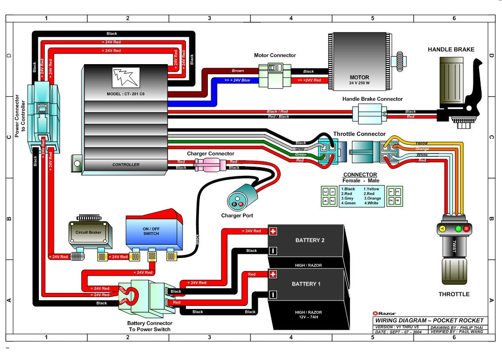
Tim...My bike came with some sort of electrical drawing, but I have no clue how to read it. How can that diagram help me to troubleshoot and electrical problem?
Fact is your right! A pictorial wiring diagram does not help to explain how things work at all. It is very handy to tell you what coloured wire goes from one point to another, but you need a better tool then just a pictorial diagram to troubleshoot.
This is where a “ladder” or logic diagram is very handy. This sort of diagram explains how the parts are interconnected to each other and how the whole electrical system functions.
Ladder diagrams are very handy for trouble shooting. I will be using this type of diagram in my video below to demonstrate trouble shooting techniques for you. I will also be posting the diagram online with this post for future reference.
Tim...Can I take two batteries and connect them in series to produce 24 VDC and use that to power my bikes starter? 24 VDC is better than 12 right?
LOL more power always sounds good, but in this case...no!
All of the components in the 12 VDC system your bike has, expect to see 12 VDC.
This is very important to all the loads as their resistance and design is based on seeing 12 VDC and only 12 VDC.
What do you think will happen if your starter motor now sees 24 VDC instead of 12 VDC?
I can tell you...it will cook! By cooking I mean that it will get nice and hot, also a little stinky as the insulation on the motor windings melts away.
If your bike is rated for 12 VDC only.
Tim...When I boost my car or bike battery am I not connecting it in series? Would that not damage my battery?
No damage will occur when you give a boost or take a boost, as long as you connect the batteries together properly! When you boost your bike’s battery you are connecting the two batteries in parallel.
Parallel means that there is more than one path of flow. So the voltage remains the same at 12 VDC. The positive terminal of one battery is connected to the positive terminal of the other battery. The same is done for the negative connection on the battery.
On our bikes all of the “loads” are connected in parallel which means that each load sees the same 12 VDC voltage applied. Electrical loads on your bike are things like the signal lights, starter, head light, speedometer. If you think of your home for a moment, all of the loads, lights etc are all connected in parallel.
When connecting the batteries in series, which you should never do!. You would be connecting the negative terminal of one battery to the positive terminal of the second battery. This gives the current only one path of flow and increase the voltage available.
As series circuits offer only one path of current flow, device connected in series on your bike have low resistance and are used to control the flow of electricity to the various loads. So all of the switches you see on your bike are connected in series to the various loads they control.
For example your headlights have a control switch, this switch is wired in series to the headlights. You will see more examples of this in my video below.
Tim...Why do some of the wires on my bike look pretty large in diameter and others look very small in diameter?
The diameter of the wire varies with the amount of current flow in it required by the load.
The system of measure used to measure wire is called the American Wire Gauge. Lower numbers mean thicker heavier wire and higher numbers mean lighter thinner wires.
Common wire sizes on your bike are 16 and 14 gauge wire.
If a wire is too thin for the amount of current flowing through it, the wire will overheat and the insulation covering the wire will melt. So...if in doubt and you are not sure of the exact wire size you are working with, always use a larger diameter instead of using a smaller diameter.
Remember that a thin wire with too much electrical current “amperage” flowing through it will overheat and cook! Not good! Unless you like tasty well done wires for dinner.
Tim...How can one of these electrical meters help me with my trouble shooting?
Handheld electrical meters are very handy toys. They meters come in a variety of forms, analog, digital, square or rectangular in shape. No matter which design you chose, they all work in a similar manner.
I would recommend that you ask Santa for one. These days you can pick up a great meter for less than $50.
Typically we use these meters to measure voltage and see if we have voltage to a component. Also we can use the volt meter to check on the charge level of the battery.
The multimeter that Santa brought you will also be able to measure resistance in the unit ohms. This is super handy as it can indicate weather or not you have a complete electrical circuit. You can also use it to see if a switch is working or not running a continuity test.
I will be demonstrating these techniques in the electrical systems video below.
So be good and maybe Santa will bring you a nice electrical multimeter this Christmas!
This weeks excellent Video on Electrical Systems can be viewed by clicking here
If you have any tech questions about our vehicles, please feel free to email them to...
Support@venommotorsportscanada.com
Check out our blog next week as we look at air and fuel filters found on your bike.
Till then, Enjoy the ride!
Tim
Technical Support Specialist
Venom Motorsports Canada
1-855-984-1612


I was wondering if you could email me the wiring diagram for my pocket bike the one in the pic is a different set up I only have one battery
I was wondering if you could email me the wiring diagram for my pocket bike the one in the pic is a different set up I only have one battery